5 minute read • published in partnership with Pilz
Insight: Implementing applications for safe human-robot collaboration
The demands on safety technology always depend on the respective application. Safe robot cells only result when the robot, tool and workpiece are assessed overall, along with the associated machinery, such as the conveyor technology for example. In practice, this means that each application requires a separate, in-depth safety-related assessment. ISO/TS 15066 already provides a normative framework; with standards for the accompanying validation, it will be easier to reconcile productivity and safety. Pilz shares its insight into how manufacturers can implement safe human-robot collaboration.
The safety fences are coming down: robots are intended to work more closely with humans. As a result, the principle of achieving safety by physically separating humans from machines no longer works. ISO/TS 15066 provides normative responses to the new challenges of human-robot collaboration (HRC). However, in practice, the road to obligatory CE marking remains a challenge.
Robots are classed as partly completed machinery under the Machinery Directive 2006/42/EC. Two standards are available for detailed industrial safety requirements: ISO 10218 “Safety of Industrial Robots” Part 1: “Robots” and Part 2: “Robot systems and integration”. The British editions of both parts are published as EN ISO 10218-1:2011 and EN ISO 10218-2:2011 and are listed as harmonised C-standards under the Machinery Directive 2006/42/EC.
Safe robot cells only result when the robot, tool and workpiece are assessed overall / Picture: Pilz
In practice, however, the existing standards proved to be inadequate for the safe implementation of an actual human-robot collaboration in which the respective work areas can overlap in terms of time and space. There was a gap in the standards, which was bridged in the spring of 2016 with the publication of the Technical Specification ISO/TS 15066 “Robots and Robotic Devices – Collaborative industrial robots”.
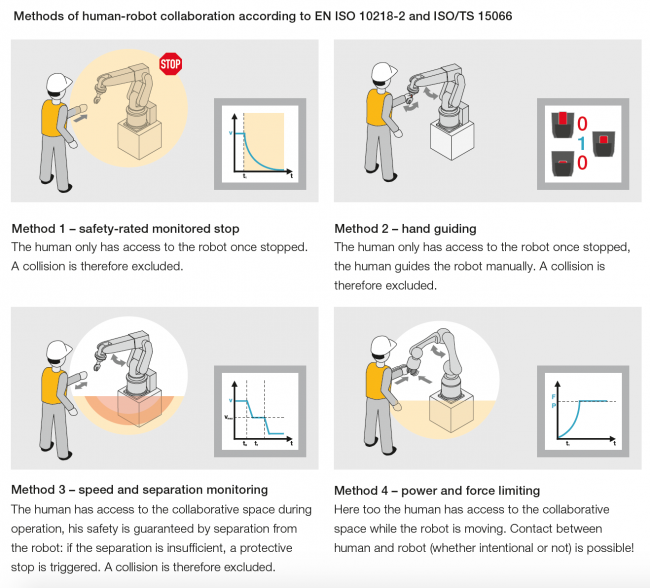
As early as the planning stage of an HRC application it is necessary to consider which of the four methods from ISO/TS 15066 is to be applied (individually or in combination). These considerations will reveal which robot type can be used: sensitive for example, i.e. with integrated safety functions, or not. Further criteria to consider when selecting the robot are the required pay-loads and operating ranges.
Start with the risk assessment
As soon as there’s an initial idea for the application there is a basis for discussion and work can already start on a risk assessment. If safety is only considered during the robot application or after the application is built, major alterations are often the result. It’s not the way to reconcile productivity and safety.
Whichever method you choose, the following applies: when implementing a robot application it’s important to remember that, in accordance with the Machinery Directive, the robot itself only constitutes a partly completed machine; only when you apply grippers or the tool required for the respective application is the robot given a specific purpose and so must be regarded as a completed machine. At this point, the integrator or user becomes the manufacturer of the machine and is responsible for CE marking, including the safety inspection. Appropriate principles for risk assessment and reduction are defined in EN ISO 12100 “Safety of Machinery”.
The iterative process is crucial for the risk assessment. This is divided into the risk analysis and risk evaluation steps. The contents of the risk assessment include identification of the applicable harmonised standards and regulations, determination of the machine’s limits, identification of all the hazards in each of the machine’s life phases, the actual risk estimation and assessment, plus the recommended approach for reducing risk. It is important that the risk assessment looks at each danger zone individually, without protective measures. An individual safety concept and system integration is developed on the basis of the risk assessment.
No safety fence – more hazards
The challenge on fenceless robot applications is that the boundaries between the two work areas of human and machine are broken down. The human’s movements must be considered in addition to the risks emanating from the robot. However, these cannot always be calculated with regard to speed, reflexes or the sudden approach of additional persons.
Even where robots have safety functions and the production technology has benefited from vast experience in designing work-stations, new questions always emerge when implementing HRC applications, particularly when method 4 is applied and collisions are therefore possible (whether intentional or otherwise). The type of collision plays a significant role. Essentially there are two different types of collision: “transient contact” between human and robot means impact from the robot. The human is hit by the robot but has the opportunity to recoil. He is not clamped. In contrast, “quasi-static” contact between a human and machine means that the human is crushed. It is not possible to avoid it and the human may be clamped and unable to free himself.
In contrast to machines that are enclosed, designers of HRC applications also need to consider the near field. It is a matter of eliminating trip hazards – due to cables for example. Any reasonably foreseeable misuse must also be taken into account. For example, a tool required for the application may occasionally be dropped.

When grippers are applied or the tool required for the respective application given to the robot, the integrator or user becomes responsible for CE marking, including the safety inspection / Picture: Pilz
Minimising collisions
As the number of collision scenarios rises, so too does the complexity as regards safety. The design of HRC applications will therefore aim to minimise collisions. In terms of the design, this may mean that robot arms are installed on the ceiling or beneath the work surface. When programming the robot, it makes sense to keep the robot’s workspace as small as possible. If the robot cannot reach, there cannot be any contact. The programmer should also set the force and speed parameters for each joint so that unnecessarily high values can be avoided. On robot arms with six or more axes, that may mean a significant amount of programming.
It depends on the validation
Validation is one of the key steps en route to CE marking. It is essential for proving that a machine complies with safety regulations. It is a time to reflect once again on the steps that have been taken previously. In contrast to the risk assessment, for validation, each danger zone is examined with protective measures. The state of the robot application must be such that it is ready for delivery.
In accordance with the standard, a variety of techniques should be used for validation, including visual inspections, practical tests and measurements. Validation includes verification of the required performance level PLr, fault simulation, overrun measurement if the HRC application is to be safeguarded using speed and separation monitoring, examination of the checklist in EN ISO 10218-2 Annex G plus collision measurement in the case of power and force limitation. The system integrator must validate over 200 points in total.
Measuring force and pressure
Finally, it is absolutely essential that a measurement procedure is used to calculate whether the potential collisions are harmless from the point of view of safety. Annex A of TS ISO/TS 15066 provides a body model with 29 specific body areas, divided into twelve body regions. The body area model provides details of the respective pain threshold for each part of the body (e.g. on the head, hand, arm or leg) with a view to force and pressure. The body region with the lowest permitted collision values is the face. In this case, a maximum force of 65N and pressure of 110N/cm2 may be applied. If the application remains within these thresholds during an encounter between human and robot, then the collision can be categorised as harmless. This is the basis for allowing the safety fences to be removed.
The technical specification stipulates the need to comply with the limit values and states which limit values apply for which body regions. However, it doesn’t describe how the pressures and forces need to be measured. Standards are currently inadequate when it comes to obtaining comparable results, no matter who performs the validation.
HRC requires its own methodology
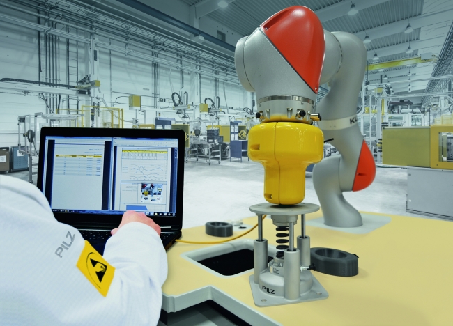
To establish an appropriate measurement procedure Pilz focused on the inspection of light beam devices, developing a separate methodology with appropriate specifications. For example, the methodology describes how to determine collision points. To guarantee the reproducibility of the measurement, a measurement is always described with the start point, collision point and end point. Pilz developed its own collision measurement set for this specific force and pressure measurement. Equipped with springs and corresponding sensors, the system measures the exact forces and pressure exerted on the human body and compares them with the limit values stated in ISO/TS 15066. The measurement device is installed at the positions determined in the risk assessment, between the robot arm and a rigid, inflexible surface. This simulates an almost static contact, e.g. the worker being crushed between the robot and plant. The collision must take place under the worst case conditions. This means that the maximum safely reduced speed must be applied, rather than the speed in the application.
If the limit values are exceeded, the dynamic performance of the robot must be reduced or additional safety measures must be installed, such as a light curtain or guard.
You can download the full white paper below